


Air-assisted sprayers discharge tank mix as tiny spray droplets into an airstream that transports the droplets to the target tree or vine canopy. The mixture of air and spray droplets, known as the spray cloud, expands in both the vertical and horizontal dimensions as it moves away from the sprayer’s outlet. The speed of the air reduces drastically after exiting the sprayer and then continues to reduce gradually with distance away from the sprayer. Because the sprayer is moving, however, the spray cloud appears as having been bent backwards.
If we consider the continuous forward movement of the sprayer to be in short steps of equal lengths, we can determine the time the sprayer spends in each step by dividing the step length by the travel speed. We can then multiply the time by the flow rates of the air and spray liquid to know the volumes of air and spray discharged in each step movement. The volume of spray is what is applied in each forward step and the volume of air is how much is available to carry the applied spray. The slower the travel speed, the higher the volume discharged; the faster the travel speed, the lower the volume discharged.
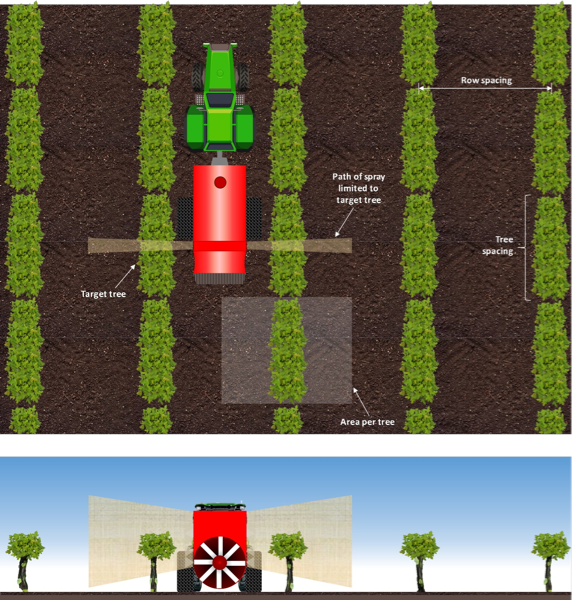
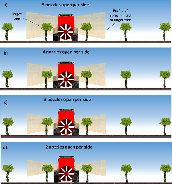
During the spray application, immediate tree or vine canopies adjacent to the sprayer are the target canopies (Figure 1, below). Each tree or vine is bound by a ground area equal to row spacing times tree spacing. It is sufficient and most efficient for the air to carry spray droplets to the target, not beyond. This is because spray droplets carried beyond the target tend to either fall to the ground or potentially drift away by the wind when they miss canopies in the subsequent rows. However, the air speed and volume should be enough to cause the spray to penetrate the target canopy. This means that travel speed and air volume of the sprayer should be matched to the canopy size and density. Also, the number of nozzles used should not result in too much spray applied over and/or under the canopy. Effective spraying will result if the spray is strategically directed toward the target.
Sprayer Calibration: What, Why, When and How
What is it? Sprayer calibration is the adjustments made to a sprayer based on measurements taken to ensure that the correct amount of material (spray mix or active ingredient) is applied.
Why is it important? Calibration is best practice in pesticide spray application. When done correctly, it is a sure way to know how much material you would actually be applying to your crop. Incorrect calibration or not calibrating at all can result in inaccurate application rate, ineffective application, and illegal residues on the treated crop. Accurate calibration will lead to effective pest control while minimizing waste and negative environmental impact. Above all, accurate sprayer calibration will ensure compliance with the law as represented by the pesticide label.
When should it be done? Ideally, sprayer calibration should be done at the beginning of the growing season and whenever there is a significant change in conditions. Examples of changes in condition that may require calibration include: Change in ground condition (e.g. soil type, soil wetness, ground cover); change in target condition (e.g. crop type, canopy size, canopy density); change in spray material condition (e.g. density). Although not all the calibration steps may be necessary in response to a change, adjustments should be made to the components that are directly affected by the change. For instance, if only ground condition has changed, then only travel speed would have to be determined again and appropriate adjustments made. However, if a global positioning system (GPS) based speedometer device or mobile app is in use, then it may not be necessary to check speed again. This is because readings of GPS-based speedometers are not affected by changes in tire traction due to ground cover.
How should it be done? A major objective of sprayer calibration is the idea of optimizing the application. There are different ways to do it, but with the same or similar outcome. The steps could be as follow: 1) determine travel speed; 2) assess air profile to determine number of nozzles; 3) select nozzles; 4) measure sprayer output; 5) adjust sprayer output; and 6) assess spray coverage.
STEP 1: Determine Travel Speed
This should be done with the sprayer tank about half-full and the fan running.
Materials needed: Measuring tape, flagging flags, stopwatch, calculator, clipboard, GPS device (e.g. smartphone).
Method 1 – Manual known distance method: Measure a known distance, D, (typically 100 or 200 feet) with a measuring tape in the orchard or vineyard where you would be spraying. Use marking flags to clearly indicate the distance. Using a stopwatch, measure the time, T, it takes for the sprayer to travel the marked distance at a preselected gear setting. Repeat this for at least three times in total and determine the average time. Calculate the speed, S, as: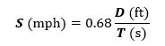
When two people are available, in addition to the operator, person A should stand adjacent to the starting flag with one hand up (Figure 2a, below). Provide enough distance for the sprayer to attain the speed before reaching the starting flag. Once a predetermined feature on the tractor/sprayer (e.g. front of tractor/sprayer, center of front wheel, etc.) reaches the starting point, person A should lower the raised hand to indicate to person B to start measuring the time with a stopwatch. Once the predetermined feature on the tractor/sprayer reaches the ending flag, person B should stop measuring the time and then record the elapsed time on a clipboard.
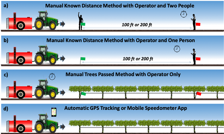
When only one person is available, in addition to the operator, fix the marking flags in the sprayer’s path (Figure 2b, above). Provide enough distance for the sprayer to attain the speed before reaching the starting flag. Once the front of the tractor touches the starting flag, start measuring the time with a stopwatch. Again, once the front of the tractor touches the ending flag, stop measuring the time and then record the elapsed time on a clipboard.
When only the operator is available, fix the marking flags in the sprayer’s path. Provide enough distance for the sprayer to attain the speed before reaching the starting flag. Maintaining sitting posture, start measuring the time with a stopwatch the moment the starting flag disappears and stop measuring just when the ending flag disappears. Record the elapsed time on a clipboard.
Method 2 – Manual tree passed method: Count about 10 or more trees or vines and fix two marking flags in an adjacent mid-row in the path of the sprayer (Figure 2c, above). Additionally, you can tie pieces of flagging tape on the vine adjacent to the marking flag to aid the operator’s visibility. Note the tree spacing, TS. Providing enough distance for the sprayer to attain speed before reaching the starting flag, measure the time it takes for the sprayer to travel the marked distance at a preselected gear setting. The number of trees passed by the sprayer, NT, is the count excluding the starting tree but including the ending tree. Repeat time measurement for a total of at least three times and determine the average. Calculate the speed as: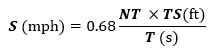
Method 3 – Automatic tracking method: Drive the sprayer for about 100 ft or more while observing the speed reading on a GPS device (a smartphone with a GPS speedometer app can be used for this). Repeat the observation for at least three times in total and determine the average. If the tractor pulling the sprayer is equipped with a GPS monitor, then speed measurement may not be necessary.
STEP 2: Assess Air Profile to Determine Number of Nozzles
Materials needed: Flagging tape, digital camera (e.g. smartphone).
Method:
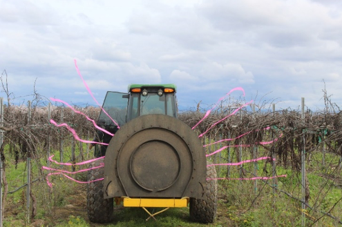
Attach about 4 feet of flagging tape to each nozzle on the sprayer manifolds. Start the fan and observe the aloft flagging tapes from behind the sprayer, see Figure 3, below. Take a photo of the scene with a camera for reviewing. From the photo, determine the number of nozzles and their position that are well directed on the target canopy. Turn off nozzles that miss the target canopy. To better understand why this is necessary, see Figure 4, below.
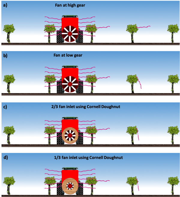
Also, attach a piece of flagging tape to the target tree or vine canopy and the next adjacent canopy in the path of the air. Drive the sprayer across the taped locations at the determined travel speed with the air running and observe the tapes on the canopies. If the tape on both canopies are sufficiently aloft, the air might be too much (Figure 5a, below). Adjust the air if the sprayer is equipped for that, considering the target canopy size and density. Otherwise, increase the travel speed to adjust the air (Figure 5b, below). Another option is to partially cover the fan inlet using a so called ‘Cornell doughnut’ (Figure 5c and 5d, below). Ideally, an automated means of adjusting the fan intake would be best.
volume.
STEP 3: Select Nozzles
Materials needed: Calculator, clipboard, nozzle catalog, nozzle selection mobile app
Method:
Knowing the desired application rate, AR, and row spacing, RS, determine the total sprayer output per side, SO, from all open nozzles as: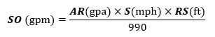
If the spray volume is intended to be uniform on each side, then divide SO by the determined number of nozzles to get the desired nozzle flow rate. Use this number to select the nozzle from a nozzle catalog.
However, SO can be split into different fractions for upper nozzles and lower nozzles. A common configuration for trees is 2/3 for upper nozzles and 1/3 for lower nozzles. Whatever the split ratio, the total should amount to the calculated SO. Various available software applications and mobile apps can be used to aid this determination.
STEP 4: Measure Sprayer Output
This should be done with the sprayer stationary. Alternate methods to that presented here exist.
Materials needed: Measuring pitcher, stopwatch, calculator, clipboard, automatic nozzle calibrator, flow meter, pressure tester.
Method:
With the sprayer running in a fixed position, confirm that the pressure gauge reading is accurate using a tool. Start spraying and collect spray water from each nozzle for 1 min using a measuring pitcher (see figure 6) and record the values in fluid ounces (oz). These should be the nozzles that will be used for the spray application. Calculate the flow rate of each nozzle as: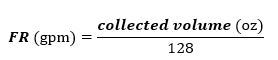
Repeat the measurement and determine the average.
Calculate the sprayer output by multiplying the average FR by N, for uniform application. For non-uniform application, do this separately for the upper and lower sections and sum them up.
Alternatively, you can automatically measure the flow rate by using a flow meter (e.g. SpotOn™ calibrator). Also, you can use a manifold patternator to observe uniformity of nozzle flow across all nozzles.
STEP 5: Adjust Sprayer Output
There are two adjustments that can be applied to the sprayer output in order to achieve the desired application rate, if the measure sprayer output is off. The first is adjusting the travel speed, while the second is adjusting the pressure.
Adjusting travel speed:
The adjusted travel speed, S2 can be obtained as:
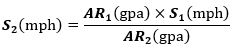 where,
AR1 = application rate obtained with the actual measured sprayer output in Step 4
AR2 = desired application rate in Step 3
S1 = travel speed measured in Step 1.
Adjusting operating pressure:
The adjusted operating, P2, can be obtained as:
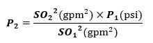
where,
SO1 = measured sprayer output in Step 4
SO2 = desired sprayer output in Step 3
P1 = initial operating pressure
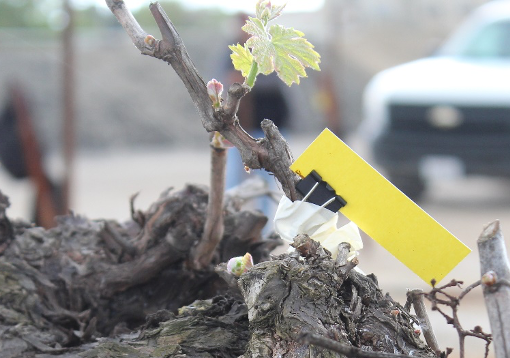
STEP 6: Assess Spray Coverage
Attach water sensitive cards (yellow cards that turn blue when moist) to different locations
in the target canopy. Run the sprayer and apply water similar to the intended application. Evaluate the spray coverage to ensure that it is suitable. Make adjustments as necessary to obtain a suitable coverage.
Once the proper settings have been obtained, maintain these settings in the actual application, making sure to factor in weather conditions. It is also important to clean the sprayer and maintain it in good working condition to ensure good performance.


 Invading California")

